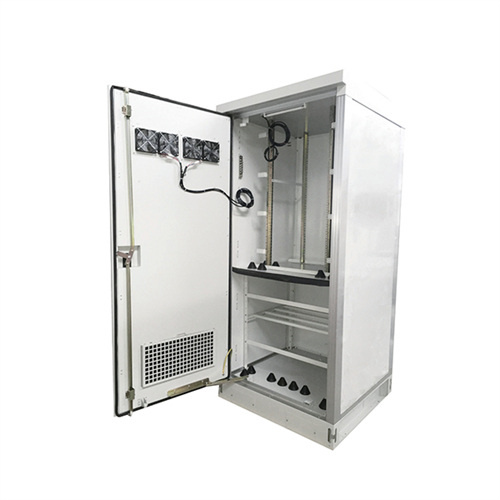
Zhongfu Circuit Photovoltaic Inverter

Boost Converter Design and Analysis for Photovoltaic Systems
Equivalent circuit diagram of PV cell. I: PV cell output current (A) Ipv: Function of light level and P-N joint temperature, photoelectric (A) Io: Inverted saturation current of diode

High-efficiency Transformerless PV Inverter Circuits
high efficiency of the inverter circuit, and the high-frequency-free ground loop voltage. Besides the high efficiency inverter circuit, the grid connection function is also the essential part of the PV

Solis: Selecting Suitable Circuit Breakers for
Mutual Heating of Circuit Breakers. For large solar PV power stations with multiple inverters, there are usually multiple circuit breakers in the distribution board, which are closely mounted next

PAPER OPEN ACCESS Design of Photovoltaic Inverter Based on
In order to meet the design requirements for the 500W inverter, the power switch tube IRF840 is selected. As shown in Figure 3, the inverter circuit is composed of four IRF840s to form four

Circuit Diagram of Solar Inverter for Home
Solar inverters are also called as photovoltaic solar inverters. These devices can help you save lot of money. The small-scale grid one have just two components i.e. the panels and inverter while the off grid systems are

PV Inverter Design Using Solar Explorer Kit (Rev. A)
The solar panel or PhotoVoltaic (PV) panel, as it is more commonly called, is a DC source with a non-linear V vs I characteristics. A variety of power topologies are used to condition power

Solar Panel Wiring Basics: Complete Guide & Tips to
This is calculated by oversizing the Short Circuit Current (Isc) by 125%, considering the number of modules in the system, as specified in the NEC 690.8(A)(1) and NEC 690.8(A)(2). There are two types of inverters

Inverter : Operating Principle,Circuit, Classification and Applications
Definition: The inverter is an electronic circuit that converts fixed DC supply to variable AC supply. The inverter is used to run the AC loads through a battery or control AC

Collaboratively Diagnosing IGBT Open-circuit Faults in Photovoltaic
Request PDF | On Oct 13, 2021, Xinyi Wang and others published Collaboratively Diagnosing IGBT Open-circuit Faults in Photovoltaic Inverters: A Decentralized Federated Learning-based

Harmonics in Photovoltaic Inverters & Mitigation Techniques
PV inverters use semiconductor devices to transform the DC power into controlled AC power by using Pulse Width Modulation (PWM) switching. Resonance: When a harmonic current ˚ow

Comparison of PI and PR Controller Based Current Control Schemes
Photovoltaic (PV) electricity is widely used because of its positive environmental impact. To properly feed this energy into the grid, an electronic power converter, known as a

6 FAQs about [Zhongfu Circuit Photovoltaic Inverter]
Who is Zhongfu Zhou?
Lecturer in Power Electronics, Electronic and Electrical Engineering Dr Zhongfu Zhou is currently a lecturer in power electronics at Swansea University. His research area has been focussing on power electronics converters and applications in renewable energy, transportation, and distribution power systems.
Can a transformerless single-phase PV inverter be controlled in standalone mode?
We propose a high-performance and robust control of a transformerless, single-phase PV inverter in the standalone mode. First, modeling and design of a DC-DC boost converter using a nonlinear back-stepping control was presented.
What is a conversion principle in a power inverter?
The conversion principle in these inverters is the use of a pulse width modulation (PWM) technique to offer a stable sinusoidal output voltage of 220 V AC to the load. Several inverters use power electronic switches such as MOSFET or IGBT in the output stage.
What is a second converter in a PV inverter system?
The second converter is an H-bridge inverter with LC filter having the role of converting continuous to alternative voltage with minimum harmonic distortion and good stability in terms of amplitude and frequency in different values of resistive loads. Block diagram of the proposed PV inverter system. 2.1. PV Array and P&O Algorithm
How to control a single-phase H-bridge inverter?
Secondly, the single-phase H-bridge inverter was controlled by using back-stepping control in order to eliminate the error between the output voltage of the inverter and the desired value, even if there is acute load variation at the output of the inverter.
What is the frequency analysis of the inverter's output voltage?
Figure 21 shows the frequency analysis of the inverter’s output voltage. The fundamental is about 310.7 V at a frequency of 50 Hz, and the THD is about 0.78%.
Related Contents
- Solar Photovoltaic Inverter Circuit Diagram
- Photovoltaic inverter consists of a boost circuit
- Photovoltaic inverter chip circuit
- Simulation circuit of photovoltaic inverter
- Photovoltaic inverter modification circuit diagram
- Photovoltaic inverter circuit test method
- Photovoltaic inverter circuit disassembly
- Photovoltaic solar inverter circuit board
- Photovoltaic inverter circuit board production
- Photovoltaic inverter control circuit
- How to adjust the circuit of photovoltaic inverter
- Photovoltaic inverter collector circuit